Hello! now
 +8619886240609(Bella)
NE555N Timer IC: Classic 8-Pin Chip for Versatile Timing, Control, and DIY Projects

- Part No.:
- NE555N
- Manufacturer:
- TAEJIN
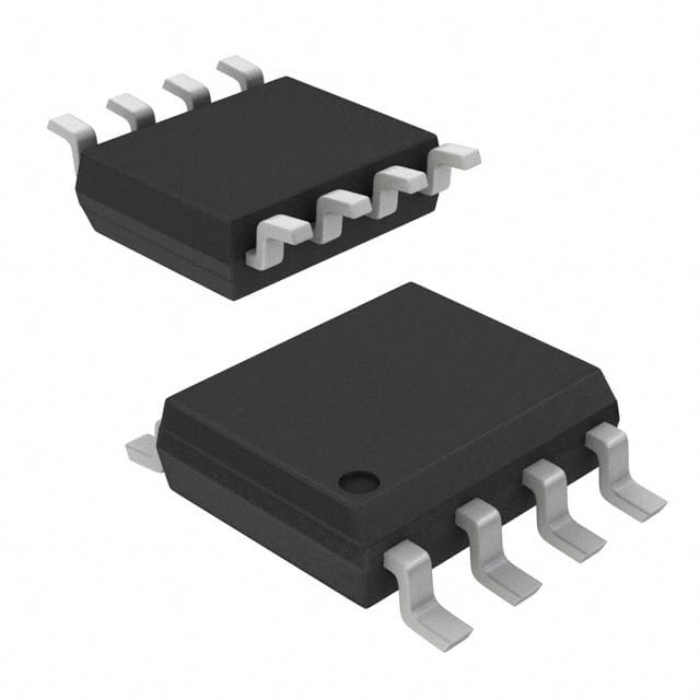
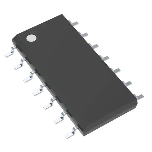
- Package:
- 8-DIP (0.300", 7.62mm)
- Description:
- IC OSC SGL TIMER 500KHZ DIP-8
- Quantity:
- Payment:

- Shipping:

Article Details
- Details
- Specifications
- Comparison
What is an NE555N Chip?
The NE555N is among the most popular and versatile 8-pin timer ICs available. This chip, first introduced in the 1970s, remains in use today, driving modern gadgets and educational electronics alike because it's both simple and cheap and it allows for an amazing range of inputs and outputs.In a few words the NE555N being a monostable and astable and also a bistable timing chip for delaying, oscillating or generating pulses with it. concise, this decisionmay be, and in the timedelay mode of operation is exact,and determined only by one external resistorand capacitor. For operation as an oscillator, boththe free running frequency and the duty cycleare precisely controlled by two external resistorsand one capacitor. The circuit can also be set and reset by falling waveforms, and the output stage can sink or source 200 mA.
NE555N Features
The NE555N is a timing chip capable of operating in single stable, non-stable and dual stable modes, the chip operates from 4.5V to 15V and can output a current of up to 200mA.Its characteristics include the following points:1.Low turn-off time
2.Maximum operating frequency greater than500 kHz
3.Timing from microseconds to hours
4.Operates in both astable and monostablemodes
5.Output can source or sink up to 200 mA
6.Adjustable duty cycle
7.TTL compatible
8.Temperature stability of 0.005% per °C
NE555N Pin Configuration and Function
The NE555N pinout is straightforward, consisting of 8 pins:
This pin is connected to the negative terminal of the power supply (0V). It serves as the reference point for the entire chip circuit.
2.Trigger – Activates the timer
Used to initiate the timing cycle. When the voltage on this pin is lower than 1/3 Vcc, it will trigger the output terminal to become a high level (in the monostable mode).
3.Output – Sends the timed pulse
It provides an output signal of the timer, which can directly drive loads such as LEDs and buzzers. The output is a high or low level, depending on the circuit mode and the input signal.
4.Reset – Resets the timer
When this pin is pulled down (below 0.7V), the output is forced to a low level and the timer immediately stops. During normal operation, it should be connected to a high level (such as directly to Vcc).
5.Control Voltage – Optional control of threshold
It is used to change the reference voltage of the internal comparator, thereby adjusting the timing accuracy. When not in use, it is usually grounded through a 0.01μF capacitor to prevent noise interference.
6.Threshold – Ends timing
It is used to detect whether the capacitor voltage has reached 2/3 Vcc. If the voltage reaches or exceeds this value, the output terminal will be forcibly set to a low level (in either monostable or non-monostable mode).
7.Discharge – Discharges the capacitor
Connect to the capacitor and discharge it when necessary (via the internal transistor). The key pin for controlling the frequency in the non-steady state mode.
8.VCC – Power supply
The input terminal of the power supply has a voltage range typically ranging from 4.5V to 15V, and the most common ones are 5V or 12V.
Understanding the NE555N pin configuration is crucial when using it in circuits. Its design allows easy implementation on breadboards and quick prototyping for beginners and hobbyists.
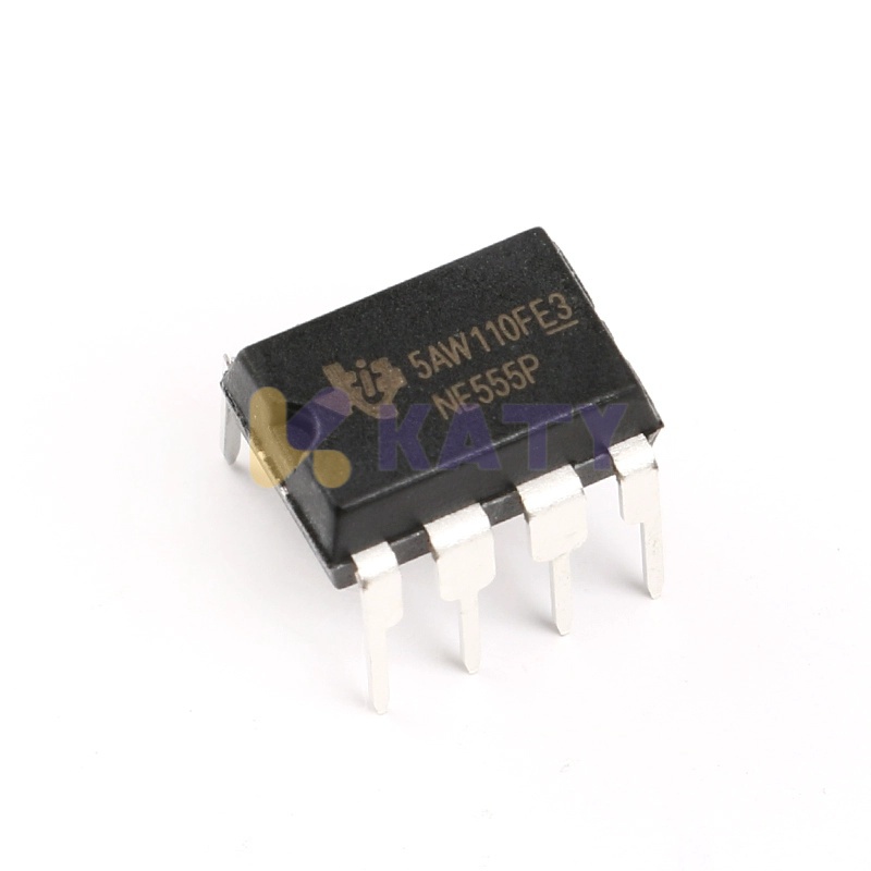
NE555N vs NE555P: What's the Difference?
A common question: What is the difference between NE555N and NE555P?While functionally similar, NE555N and NE555P differ mainly in manufacturer and internal architecture. The NE555P, produced by Texas Instruments, is typically more power-efficient and may feature a CMOS design. The NE555N, on the other hand, is widely available from various brands and usually based on bipolar junction technology, making it a better choice for high-speed applications.
NE555N: Bipolar Transistor (BJT) structure
Advantages:
Strong drive output (up to 200mA)
Fast switching speed, suitable for high-frequency oscillation circuits
Strong anti-interference ability, good stability
Disadvantages:
High static current (generally >2mA), not suitable for battery-powered applications
Heats slightly more than the CMOS version
NE555P: CMOS Technology Structure
Advantages:
Extremely low power consumption (<100μA)
More suitable for 3.3V or low-voltage power supply
More applicable to portable devices and battery circuits
Disadvantages:
Weak driving capability, output current usually <100mA
More sensitive to power supply ripple and interference
In other words:
NE555P vs NE555N = CMOS vs Bipolar; efficiency vs speed.
The NE555N is suitable for circuits that need a large drive capability, like industrial equipment, power control modules, frequency control systems, and audio pulse output.
Such as: For Arduino projects, Sensor light boards, Industrial automation, LED Display boards etc.. and all Other kinds of electronic system or experiment. 2-100Hz input Square wave/ Pulse can be applied. NE555P can be used.
Real-World Applications and Projects
The NE555N has powered everything from DIY gadgets to vintage computers like the Atari XE (notably listed as "NE555N 8 pin timer IC Atari XE").There are several NE555N timer circuit applications that are commonly used:
1.LED flashers:
NE555N non-steady state mode (astable that is) and a level goes out and the low level continues. LED on-off can produce flashing rhythm.
Pulse-width modulation (PWM) controllers:
PWM (pulse-width modulation) is a method of controlling voltage or power as the duty cycle is modified. The NE555N is able to produce square wave signal of adjustable pulse width which can drive the LED light and motor whose rotational speed is proportional to the pulse width.
3.Tone generators
Using the NE555N to produce a certain frequency of audio signal to drive the buzzers or speakers and make sounds, widely applied to sound alarm, electric bell, or musical toy, etc.
4.Delay timers
In monostable mode, after receiving a trigger signal, NE555N is able to output a high-level pulse of fixed duration for delaying the shutdown or startup of the apparatus.
5.Frequency counters
As a non steady state frequency generator, the NE555N is also applicable. It may also be used for the simple frequency counter by counting the output signal frequency.
6.Simple games and alarms
The time-delay control, sound effect and light-flashing which are controlled by NE555N can be apply to all kinds of the electronic products for the refit of factory or the traction of home.
Arduino Compatibility and Breadboard Friendliness
The combination of the NE555N Arduino serves as an introduction to code-controlled hardware. Beginners love that it's a snap to plug the IC NE555N into a breadboard, and that it allows Arduino Boards to control real-world events through simple timing-based circuits.
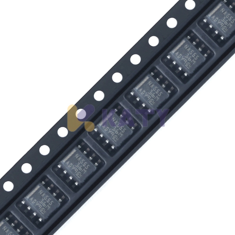
NE555N Variants and Markings
When shopping online, you might find variations like:NE555N S7142
NE555N KGX036 CHN
NE555N AVE
These numbers usually represent production batch numbers or regional production codes (such as CHN for China).
There are some fakes labelled NE555N on the market. These two kinds of products have low quality in chip encapsulates and unstable use function.
It is suggested that you check the datasheet to compare the model, packages, and the package control number such as KGX036(CHN), S7142, and so on.
Beware of NE555N fan fake ICs – read reviews and buy from reputable sources. HK KATY don't sell the composite imitation of products. Buy with confidence actual product 100% Original You can.
NE555N IC: Simple Yet Powerful
While most may assume that it has been obsolesced by newer offerings, the NE555N continues to serve as a general-purpose chip for both hobbyist and industry engineers. Time theory, your first Arduino NE555N project, or you're just repairing an Atari XE, this chip is going to do it all.Knowing its datasheet, pinout, pins description and application and comparison with other variants of timer IC helps you to explore options and select the right variant for your application.
So there you have it, the time keeping NE555N, it keeps time like a pro – in a flashing.LED circuit, a motor delay circuit or a sound output circuit.
- Product attributes
- Attribute value
- Manufacturer:
- TAEJIN
- Series:
- -
- Package/Case:
- 8-DIP (0.300", 7.62mm)
- Packaging:
- Tube
- Part Status:
- Active
- Resistance:
- 555 Type, Timer/Oscillator (Single)
- Tolerance:
- -
- Composition:
- 2V ~ 18V
- Features:
- 300 µA
- Temperature Coefficient:
- -20°C ~ 70°C
- Operating Temperature:
- 8-DIP
- Supplier Device Package:
- Through Hole
- Power (Watts):
- 500kHz
- Ratings:
- -
- Size / Dimension:
- -
- Height - Seated (Max):
- Number of Terminations:
- Failure Rate:
| Image | |
| Part Number | NE555N |
| Manufacturer | TAEJIN |
| Series | - |
| Package/Case | 8-DIP (0.300", 7.62mm) |
| Packaging | Tube |
| Part Status | Active |
| Type | 555 Type, Timer/Oscillator (Single) |
| Count | - |
| Voltage - Supply | 2V ~ 18V |
| Current - Supply | 300 µA |
| Operating Temperature | -20°C ~ 70°C |
| Supplier Device Package | 8-DIP |
| Mounting Style | Through Hole |
| Frequency | 500kHz |
| Grade | - |
| Qualification | - |

- Fast Shipping Fast and convenient door to door delivery.

- Paypment Security More than 5 different secure payment methods.

- Strictly Quality Control 365 days After-Sales Service and Warranty

- Simple And Professional One-stop Electronics Procurement Solutions.