STM32H757XIH6 – Cortex-M7 + Cortex-M4 Dual-Core High-Performance MCU

- Part No.:
- STM32H757XIH6
- Manufacturer:
- STMicroelectronics
- Package:
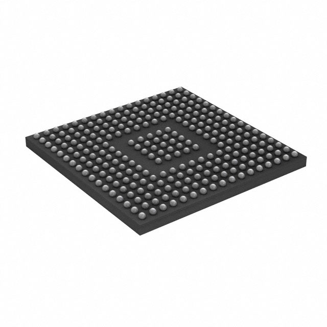
- 265-TFBGA
- Description:
- IC MCU 32BIT 2MB FLASH 265TFBGA
- Quantity:
- Payment:

- Shipping:

Article Details
- Details
- Specifications
- Comparison
Do you have any doubts about how to simultaneously complete complex computing/communication processing and real-time control/peripheral management tasks on a single chip? Then you can try the STM32H757XIH6. The STM32H757XIH6 is ahigh-performance dual-core main control MCUlaunched by STMicroelectronics, featuring dual-core collaboration and peripheral integration capabilities, and is suitable for applications that require "high reliability + high performance". It avoids the system's real-time control being blocked by computing tasks, making the system more stable, with faster response, reducing the number of external chips, lowering BOM costs and system complexity.
Understanding the dual-core architecture of STM32H757XIH6
What is a dual-core architecture?
The dual-core architecture of STM32H757XIH6 integrates a high-performance main core (Cortex-M7) and a real-time control core (Cortex-M4) within the same MCU. The two cores can operate independently, share some resources, and work collaboratively. Without compromising real-time performance, it significantly enhances the overall computing power and complexity handling capacity of the system.
In the storage architecture, how do the two cores "fulfill their respective roles"?
- Private storage:ITCM/DTCM provides dedicated SRAM for M7 and M4.
- Shared storage:The dual-core can simultaneously access AXI SRAM/SRAM for data exchange, parameter transfer and status synchronization.
- External storage:QSPI Flash and SDRAM are usually managed by M7, and M4 should minimize direct access.
Notes:The block diagram in the datasheet can help you intuitively understand that the two cores do not slow down each other.
How to "properly use" the STM32H757XIH6?
1. Reasonably divide the dual-core tasks
- Do not let both cores handle large tasks. Real-time tasks should be given priority to M4, while computing power, UI, and network tasks should be assigned to M7.
- The advantage of M4 is its fast interrupt response, simple architecture and strong determinism, and it is less likely to be interfered by cache and DMA.
- The advantage of M7 is its high main frequency, with I/D Cache, and it is suitable for big data algorithms.
Utilize shared SRAM, hardware semaphores, Mailbox / message queues.
3. Hardware Design and Required Peripheral Components (Critical)
- External QSPI Flash
- For display: SDRAM
- Stable power supply + multiple decoupling
- High-speed interface PCB routing
- Ethernet: impedance control, differential routing
- SDRAM: equal length, topological planning
- USB: differential, ESD protection
How does the STM32H757XIH6 operate reliably, stably and for an extended period of time?
Absolute Maximum Ratings

working principle
The working principle of STM32H757XIH6 is based on a complete working path from power-on - startup - dual-core concurrent operation - peripherals and data flow - exceptions and recovery. It achieves stable and parallel operation for complex calculations and real-time control.
1.Power-on → Power monitoring → Safety reset
- Power-on process: Each power domain (VDD / VDDA / VDDCORE) is established, the internal power management circuit starts to work, the POR / BOR (power-on / undervoltage reset) circuit takes effect, the chip is forcibly kept in the reset state until the voltage stabilizes.
- Determination of the startup core: Cortex-M7 is the main startup core, Cortex-M4 is in the idle state by default. The dual-core does not start simultaneously but is controlled by the main core, from power-on - startup - concurrent operation of peripherals and data flow - exceptions and recovery of the secondary core.
- The initialization responsibilities of M7: Clock system initialization (PLL / HSE / HSI), power mode configuration, SRAM / Cache settings, peripheral clock enabling, dual-core communication resource initialization (shared RAM / HSEM)
- M7 starts M4: M7 writes the program address of M4 to the designated register - releases the reset control over M4 - M4 begins to execute its own program independently
- The three reasons for the non-conflicting parallel operation: independent execution units, hierarchical storage structure, and multiple bus matrix
- Basic operation mode: M7 is responsible for GUI, Ethernet/USB, data processing. M4 is responsible for sampling, PWM/controls, and real-time protection.
- One core writes data to the shared SRAM
- Using hardware semaphores (HSEM) to lock resources
- After the data is written, release the HSEM
- Notify the other core to read
- The CPU is responsible for configuration
- The peripheral devices operate independently
- DMA is responsible for data transfer
- Watchdog Mechanism
- IWDG / WWDG Independent of CPU
- If the program malfunctions and the dog is not fed → Automatic reset
- Power supply and clock abnormality handling
- Under-voltage → BOR reset
- Clock abnormality → Automatic switching / reset
Common Questions about STM32H757XIH6
Q1: How many power supplies does STM32H757XIH6 require? Can only one be used?It is not recommended to use only one. STM32H757XIH6 adopts a multi-power domain design. To enhance stability and anti-interference capabilities, simplified power supply may result in ADC accuracy reduction or system instability.
Q2: Can IO be connected to 5V devices?
No, the input voltage of GPIO cannot exceed VDD + 0.3V. 5V signals must be converted or divided by a voltage divider to avoid long-term damage risks.
Q3: Can GPIO directly drive relays or motors?
No, GPIO has limited driving current. Relays, motors, LED lights, etc. must be isolated driven through transistors or MOSFETs.
Q4: Does STM32H757XIH6 support industrial temperature?
STM32H757XIH6 supports –40°C to +85°C, suitable for long-term operation environments such as industrial control and automation equipment.
- Product attributes
- Attribute value
- Manufacturer:
- STMicroelectronics
- Series:
- STM32H7
- Package/Case:
- 265-TFBGA
- Packaging:
- Tray
- Part Status:
- Active
- Resistance:
- Not Verified
- Tolerance:
- ARM® Cortex®-M4/M7
- Composition:
- 240MHz, 480MHz
- Features:
- CANbus, EBI/EMI, Ethernet, I2C, IrDA, LINbus, MDIO, MMC/SD/SDIO, QSPI, SAI, SPDIF, SPI, SWPMI, UART/USART, USB OTG
- Temperature Coefficient:
- Brown-out Detect/Reset, DMA, I2S, LCD, POR, PWM, WDT
- Operating Temperature:
- 168
- Supplier Device Package:
- 2MB (2M x 8)
- Power (Watts):
- 32-Bit Dual-Core
- Ratings:
- FLASH
- Size / Dimension:
- -
- Height - Seated (Max):
- 1M x 8
- Number of Terminations:
- 1.62V ~ 3.6V
- Failure Rate:
- A/D 36x16b; D/A 2x12b
| Image | |
 |
|
 |
| Part Number | STM32H757XIH6 | STM32H757XIH6A | STM32H757XIH6TR | STM32H757XIH6U |
| Manufacturer | STMicroelectronics | STMicroelectronics | STMicroelectronics | STMicroelectronics |
| Package/Case | 265-TFBGA | - | 265-TFBGA | 265-TFBGA |
| Series | STM32H7 | - | STM32H7 | STM32H7 |
| Packaging | Tray | Tray | Tape & Reel (TR) | Tray |
| Part Status | Active | Active | Active | Active |
| Programmable | Not Verified | - | - | Not Verified |
| Core Processor | ARM® Cortex®-M4/M7 | - | ARM® Cortex®-M4, Cortex®-M7 | ARM® Cortex®-M4/M7 |
| Speed | 240MHz, 480MHz | - | 240MHz, 480MHz | 240MHz, 480MHz |
| Connectivity | CANbus, EBI/EMI, Ethernet, I2C, IrDA, LINbus, MDIO, MMC/SD/SDIO, QSPI, SAI, SPDIF, SPI, SWPMI, UART/USART, USB OTG | - | CANbus, EBI/EMI, Ethernet, I2C, IrDA, LINbus, MDIO, MMC/SD/SDIO, QSPI, SAI, SPDIF, SPI, SWPMI, UART/USART, USB OTG | CANbus, EBI/EMI, Ethernet, I2C, IrDA, LINbus, MDIO, MMC/SD/SDIO, QSPI, SAI, SPDIF, SPI, SWPMI, UART/USART, USB OTG |
| Peripherals | Brown-out Detect/Reset, DMA, I2S, LCD, POR, PWM, WDT | - | Brown-out Detect/Reset, DMA, I2S, LCD, POR, PWM, WDT | Brown-out Detect/Reset, DMA, I2S, LCD, POR, PWM, WDT |
| Grade | - | - | - | - |
| Number of I/O | 168 | - | 168 | 168 |
| Program Memory Size | 2MB (2M x 8) | - | 2MB (2M x 8) | 2MB (2M x 8) |
| Core Size | 32-Bit Dual-Core | - | 32-Bit Dual-Core | 32-Bit Dual-Core |
| Program Memory Type | FLASH | - | FLASH | FLASH |
| EEPROM Size | - | - | - | - |
| Operating Temperature | -40°C ~ 85°C (TA) | - | -40°C ~ 85°C (TA) | -40°C ~ 85°C (TA) |
| RAM Size | 1M x 8 | - | 1M x 8 | 1M x 8 |
| Qualification | - | - | - | - |
| Oscillator Type | Internal | - | External, Internal | Internal |
| Voltage - Supply (Vcc/Vdd) | 1.62V ~ 3.6V | - | 1.62V ~ 3.6V | 1.62V ~ 3.6V |
| Data Converters | A/D 36x16b; D/A 2x12b | - | A/D 36x16b Sigma-Delta; D/A 2x12b | A/D 36x16b; D/A 2x12b |
| Mounting Style | Surface Mount | - | Surface Mount | Surface Mount |
| Supplier Device Package |
inventory:412
Please send an inquiry. Send us your inquiry, and we will respond immediately.
-
ATTINY4-TSHR
Microchip Technology
-
ATTINY10-TSHR
Microchip Technology
-
ATTINY10-TS8R
Microchip Technology
-
ATTINY202-SSNR
Microchip Technology
-
ATTINY202-SSFR
Microchip Technology
-
ATTINY402-SSNR
Microchip Technology

- Fast Shipping Fast and convenient door to door delivery.

- Paypment Security More than 5 different secure payment methods.

- Strictly Quality Control 365 days After-Sales Service and Warranty

- Simple And Professional One-stop Electronics Procurement Solutions.